Medical electronics are becoming smaller, lighter, smarter, and more functionally integrated. Products such as patient monitoring equipment, diagnostic instruments, wearable healthcare devices, medical sensors, portable testing devices, laboratory instruments, and control modules often require compact internal structures and highly reliable electrical connections. In these applications, traditional cable connections or multiple rigid boards may take up too much space, increase assembly complexity, and create more potential failure points.
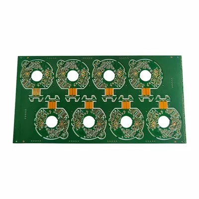
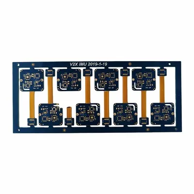
Our Rigidflex PCB for Medical Devices solution is designed to help customers solve these challenges by combining rigid board areas with flexible circuit sections. This structure allows the PCB to fold, bend, and fit into compact medical equipment while supporting stable signal transmission and long-term reliability. For medical electronics customers, the key concern is not only whether the board can be manufactured, but whether it can support real device testing, assembly, repeated production, and long-term use.
Common customer pain points include limited internal space, connector failure, unstable signal transmission, bending damage, rigid-flex transition cracking, material inconsistency, and unstable batch quality. We focus on these issues through DFM engineering review, material traceability, bend reliability control, strict inspection, and prototype-to-mass-production support.
Space Saving
Space saving is one of the main reasons medical electronics engineers choose rigid-flex PCB structures. Many medical products need to integrate sensors, displays, batteries, control modules, and communication functions into very limited space. If the product uses several rigid boards connected by cables, the internal layout may become bulky and difficult to assemble.
Rigid-flex design helps combine multiple functional areas into one integrated circuit structure. Rigid sections can be used for component mounting, while flexible sections can connect different areas and bend into the device enclosure. This allows customers to reduce product thickness, simplify internal wiring, and improve design freedom.
For portable monitors, wearable medical electronics, compact diagnostic tools, and small sensor modules, saving space can directly improve product usability and appearance. More importantly, it can also reduce assembly steps and help engineers design more stable internal structures.

Connector Reduction
Connectors and cables are often used to connect separate circuit boards, but they may become weak points in medical electronic products. Over time, connectors may loosen, oxidize, suffer poor contact, or fail due to vibration, repeated handling, or assembly errors. In products that require stable long-term operation, reducing connector-related failure risks is very important.
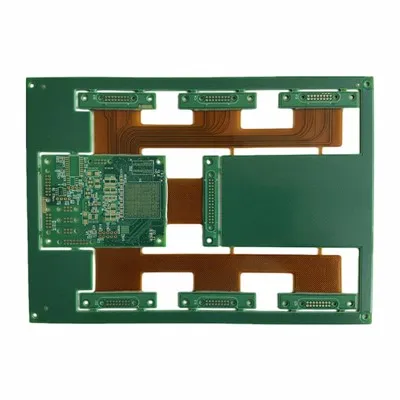
Rigid-flex PCB design can replace some cable and connector connections by integrating flexible interconnection directly into the board. This helps reduce the number of parts, simplify assembly, improve internal connection stability, and reduce the chance of contact failure.
For medical customers, connector reduction is not only a space-saving benefit. It also supports reliability, repeatability, and easier product assembly. This is especially valuable for equipment that must operate accurately and consistently, such as monitoring devices, diagnostic modules, medical sensors, and portable healthcare products.

Bend Reliability
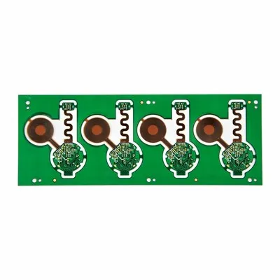
Bend reliability is a major concern in medical rigid-flex PCB projects. The flexible section may need to bend during installation, remain folded inside the equipment, or support a compact mechanical structure. If the bend area is not designed correctly, it may lead to copper cracking, coverlay damage, delamination, or open circuits.
Reliable bending performance depends on the material, copper type, copper thickness, flex layer structure, bend radius, trace direction, and final installation method. Components, vias, solder joints, and sharp corners should generally be kept away from active bending areas. The design should also avoid sudden thickness changes that create mechanical stress.
For static bending applications, the flexible area may only bend once during installation and then remain fixed. For applications involving repeated movement, material selection and bend radius control become even more important. We review the bend area before production to help customers reduce hidden failure risks.
Rigid-Flex Transition Control

The rigid-flex transition area is one of the most critical reliability points in the entire PCB structure. This is where the rigid section and the flexible section meet. If the transition area is not designed or manufactured properly, it may become a stress concentration point and cause cracking, copper fatigue, delamination, or intermittent electrical failure.
Good transition control requires proper stack-up design, coverlay alignment, copper routing, material compatibility, and stress relief. Heavy components, connectors, vias, and solder joints should not be placed too close to high-stress transition zones whenever possible. The transition area should also avoid sudden structural changes.
For medical equipment, some failures may not appear during initial inspection but may occur after assembly, testing, handling, or long-term use. That is why transition area control should be reviewed during the engineering stage, not after production problems appear.
Stable Signal Performance
Many medical electronic products depend on accurate signal collection, stable data transmission, and consistent electrical performance. Patient monitoring systems, diagnostic instruments, sensor modules, and laboratory testing equipment may require low-noise signal paths, controlled impedance, and reliable interconnection between different functional areas.
A Rigid-Flex Circuit Board for Medical Devices can help reduce connector-related signal loss and improve internal connection stability. However, signal performance still depends on proper stack-up design, material selection, trace width, spacing, copper balance, and production consistency.
For signal-sensitive projects, we can review stack-up requirements, impedance needs, routing density, and layer structure before production. This helps customers reduce risks such as signal distortion, impedance deviation, unstable readings, or performance variation between production batches.
Material Traceability
Material traceability is very important for medical electronics projects. Once a product has passed validation, customers usually want future batches to use stable materials and controlled production records. Unexpected material changes may affect electrical performance, assembly behavior, reliability testing, or product approval.
Common material choices include FR4 or High-Tg FR4 for rigid areas, polyimide for flexible areas, RA copper for better bending reliability, ED copper for static bending structures, coverlay for circuit protection, and ENIG for fine-pitch solderability. The right selection should depend on bending requirement, signal performance, operating temperature, assembly process, and long-term supply needs.
|
Material / Structure |
Main Function |
Customer Benefit |
|
FR4 / High-Tg FR4 |
Rigid support and dimensional stability |
Suitable for component mounting and control areas |
|
Polyimide Flex Layer |
Flexibility and heat resistance |
Supports bending and compact installation |
|
RA Copper |
Improved flex reliability |
Suitable for higher bending requirements |
|
ED Copper |
Cost-effective for static structures |
Suitable for fixed installation |
|
Coverlay |
Protects flexible traces |
Improves insulation and bend area protection |
|
ENIG Surface Finish |
Flat soldering surface |
Suitable for fine-pitch components and reliable assembly |
Traceable materials and clear production records help customers manage repeat orders, quality reviews, and long-term product stability.
Strict Quality Control
Strict quality control is essential for medical rigid-flex PCB projects. Customers need confidence that each board can support device testing, assembly, and long-term operation. Quality control should cover not only open and short circuit testing, but also material condition, layer registration, flex area quality, transition area stability, solderability, dimensional accuracy, and batch consistency.
Our quality control process can include incoming material inspection, inner layer inspection, lamination control, drilling and plating inspection, coverlay alignment inspection, AOI inspection, electrical testing, dimensional inspection, surface finish inspection, and final visual inspection. For projects with higher requirements, impedance testing, micro-section analysis, or additional inspection reports can also be arranged.
|
Quality Focus |
Purpose |
|
Electrical testing |
Reduces open and short circuit risks |
|
Flex area inspection |
Helps identify bending-related defects |
|
Transition area control |
Reduces cracking and delamination risks |
|
Dimensional inspection |
Supports accurate medical device assembly |
|
Surface finish inspection |
Improves solderability and assembly reliability |
|
Batch record control |
Supports repeat order consistency and traceability |
Good quality control helps reduce customer-side failures, improve validation efficiency, and support stable long-term cooperation.
DFM Engineering Support
DFM engineering support is especially important for rigid-flex PCB projects because many risks begin at the design stage. A design may be electrically correct, but still create manufacturing, bending, assembly, or reliability problems.
Our DFM review can check bend radius, rigid-flex transition structure, stack-up design, via placement, trace routing, coverlay openings, solder mask requirements, surface finish suitability, impedance requirements, and assembly-related risks. For compact medical electronics, this review can help avoid repeated redesign, production delays, and unexpected reliability problems.

Early engineering review also helps customers choose suitable materials, define realistic tolerances, and prepare for future volume production. A strong DFM process improves the chance that the first prototype will be useful for real testing.

Prototype to Mass Production
Medical electronics projects usually move through several stages, from prototype testing to engineering validation, pilot production, and mass production. During the prototype stage, customers focus on mechanical fit, bending behavior, electrical function, and assembly feasibility. During pilot production, process stability and repeatability become more important. In mass production, customers care about consistency, traceability, delivery stability, and long-term supply.
For customers developing a Rigidflex Circuit for Medical Devices, we support the complete process from early design review to production scaling. By keeping material requirements, stack-up details, bend radius, inspection standards, and engineering records clear, we help reduce risks when moving from sample approval to repeated production.
Batch Consistency
Batch consistency is one of the most important concerns for medical device customers. A prototype may pass testing, but if future batches vary in material, thickness, copper quality, solderability, or bend performance, the customer may face revalidation work, assembly issues, or product instability.
We focus on controlled documentation, material traceability, production process consistency, inspection standards, and repeat order management. Stable batch quality helps customers reduce qualification risks and maintain predictable product performance over time.
Consistent production is not only a manufacturing goal; it is also a key part of supporting medical customers through long product life cycles.
FAQ
Q1: Why are rigid-flex PCBs used in medical electronics?
They help save space, reduce connectors, simplify assembly, and improve internal connection reliability in compact medical equipment.
Q2: What medical applications can use this type of PCB?
Common applications include patient monitors, diagnostic instruments, wearable healthcare devices, medical sensors, portable testing devices, laboratory equipment, and control modules.
Q3: Why is bend reliability important?
Poor bend design may cause copper cracking, delamination, coverlay damage, or open circuits. Proper bend radius and flex area design help improve long-term reliability.
Q4: What is the most critical area in a rigid-flex PCB?
The transition area between rigid and flexible sections is very important because it can become a stress concentration point if not designed properly.
Q5: Can controlled impedance be supported?
Yes. For signal-sensitive medical electronics, stack-up review and controlled impedance can be supported according to project requirements.
Hot Tags: rigid-flex PCB for medical devices, China rigid-flex PCB for medical devices manufacturers, suppliers, factory