Automotive electronics are becoming more compact, intelligent, and functionally integrated. Modern vehicles use electronic modules for sensing, lighting, battery management, ADAS, cameras, infotainment, dashboard control, power control, and safety-related systems. In many of these applications, traditional wiring harnesses and multiple rigid boards can take up too much space, increase assembly complexity, and create more potential failure points. This is why rigid-flex circuit technology is increasingly used in vehicle electronic products that require compact structure, reliable connection, and long-term stability.
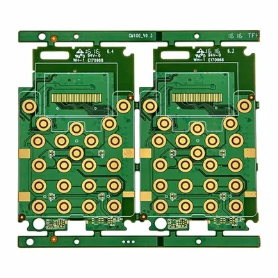
Our Automotive Rigid-Flex PCB solutions are designed for customers who need strong mechanical support, flexible interconnection, stable signal transmission, and reliable performance under demanding vehicle environments. By combining rigid board sections with flexible circuit areas, this structure helps reduce connectors and cables while supporting compact module design.
Customers usually care about more than whether the board can be manufactured. They want to know whether it can withstand vibration, temperature changes, bending stress, long working hours, and mass production requirements. We focus on these real pain points by providing material selection support, DFM review, transition area control, bend reliability review, strict quality inspection, and prototype-to-mass-production support.
Space Saving
Space saving is one of the main reasons vehicle electronics manufacturers choose rigid-flex circuit designs. Automotive modules are often installed in limited spaces, such as sensor housings, camera modules, lighting systems, dashboard areas, door control units, BMS modules, and compact control boxes. Traditional board-to-board connectors and wire harnesses may increase product size and limit design flexibility.
Rigid-flex construction allows different rigid areas to be connected through flexible sections, enabling the circuit to fold, bend, or fit into complex internal structures. This helps engineers reduce the overall module size and create cleaner internal layouts. For applications such as automotive cameras, sensors, lighting controllers, and smart cabin electronics, saving space can directly improve product design freedom and assembly efficiency.
The customer pain point is usually clear: the product needs more functions, but the available space does not increase. A well-designed rigid-flex solution helps solve this conflict by improving internal integration without sacrificing electrical connection reliability.
Connector Reduction
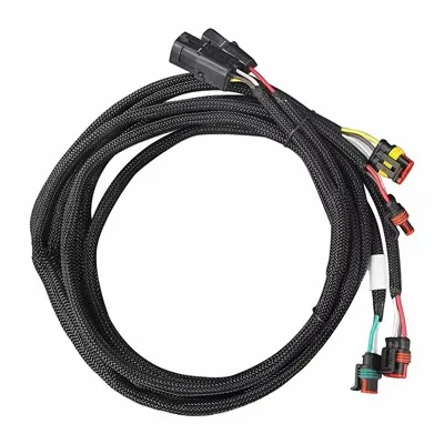
Connectors and wire harnesses are common in automotive electronics, but they can also introduce risks. In a vehicle environment, connectors may face vibration, dust, humidity, oxidation, poor contact, and mechanical loosening. Each extra connector also adds assembly steps, inspection points, and possible failure locations.
Rigid-flex circuit design can reduce the number of connectors and cables by integrating flexible interconnection directly into the board structure. This can help simplify assembly, reduce manual wiring, improve signal consistency, and lower the risk of connection-related failures.
For customers, connector reduction is not only about saving space. It also helps improve reliability and production efficiency. Fewer connectors mean fewer parts to manage, fewer assembly errors, and fewer long-term contact problems. This is especially important for vehicle systems that must remain stable during vibration and long-term operation.

Vibration Resistance
Automotive electronics must operate in environments where vibration is common. Engine vibration, road impact, vehicle movement, and long-term mechanical stress can affect PCB reliability. Customers often worry that solder joints, connectors, flex areas, or transition zones may fail after repeated vibration.
Rigid-flex structures can help improve reliability by reducing separate cables and connector interfaces. However, the design still needs careful review. Flexible areas should be routed and supported properly, and rigid sections should provide stable component mounting. The transition between rigid and flexible areas must avoid excessive stress concentration.
For applications such as sensors, lighting modules, camera systems, and vehicle control units, vibration resistance is a key performance concern. We help customers review board structure, bend zones, transition areas, and assembly requirements to reduce mechanical failure risks before production.
Thermal Stability
Automotive electronic products may face heat from the vehicle environment, nearby power components, LED lighting, battery systems, or long operating hours. Thermal stress can affect material stability, solder joints, copper reliability, and long-term performance.
Customers often ask whether the selected material can support temperature changes and whether the board can remain stable after thermal cycling. For this reason, material selection is important. FR4 or High-Tg FR4 can be used in rigid sections according to the thermal requirement, while polyimide is commonly used in flexible areas due to its flexibility and heat resistance.
Thermal stability is especially important for lighting control, BMS, power-related modules, and engine-adjacent electronics. A reliable design should consider material Tg, copper thickness, stack-up structure, surface finish, and final operating environment.

Bend Reliability
Bend reliability is a major concern for customers using rigid-flex circuits in vehicle electronics. The flexible section may need to bend during installation or remain folded inside the product structure. If the bend area is not designed correctly, it may cause copper cracking, coverlay damage, delamination, or open circuits.
Good bend reliability depends on proper bend radius, copper type, flex layer thickness, trace direction, and stack-up design. Components, vias, solder joints, and sharp trace corners should generally be kept away from active bending areas. The design should also avoid sudden thickness changes that may create stress.
For fixed installation applications, the board may only bend during assembly and then remain stable. For applications involving repeated movement, the bending requirement becomes more demanding. Understanding the final use condition helps select the right material and structure.

Rigid-Flex Transition Control
The transition area between rigid and flexible sections is one of the most critical reliability points. Customers often worry about cracking, copper fatigue, delamination, or intermittent failure near this area. These problems may not appear during the first inspection but can occur after vibration, bending, temperature changes, or long-term use.
Proper transition control includes stack-up review, copper routing design, coverlay alignment, bend radius control, and stress relief. The transition area should avoid heavy components, connectors, vias, and sharp mechanical changes whenever possible. If the design places stress directly at the transition zone, long-term reliability may be affected.
This part of the board needs special attention during both design review and production. Early DFM support can help identify hidden risks before samples are built.
Stable Signal Performance
Automotive electronics often involve signal transmission, sensing, data communication, control functions, and power management. Signal instability may affect cameras, sensors, ADAS modules, infotainment systems, dashboards, or communication-related circuits. Customers want to know whether the circuit can support stable performance under real vehicle conditions.
An Automotive Rigidflex Circuit Board can help improve signal stability by reducing connector interfaces and shortening internal connection paths. For signal-sensitive applications, controlled impedance, proper stack-up design, copper balance, fine-line routing, and stable material selection are important.
|
Application Area |
Main Customer Concern |
|
Automotive sensors |
Stable signal, compact size, reliable connection |
|
Camera modules |
Dimensional accuracy, fine-pitch routing, signal quality |
|
BMS modules |
Electrical safety, current stability, long-term reliability |
|
ADAS electronics |
Signal integrity, high-density routing, controlled impedance |
|
Lighting control |
Heat resistance, vibration reliability, stable operation |
|
Infotainment systems |
Connector reduction, signal stability, assembly efficiency |
By understanding the application, we can recommend suitable design and manufacturing solutions for both electrical and mechanical performance.
Material
Common material and structure options include FR4 or High-Tg FR4 for rigid areas, polyimide for flexible sections, RA copper for better bending reliability, ED copper for static bending applications, coverlay for insulation and flex protection, and ENIG for fine-pitch solderability.
|
Material / Structure |
Main Function |
Customer Benefit |
|
FR4 / High-Tg FR4 |
Rigid support and thermal stability |
Suitable for component mounting and control areas |
|
Polyimide Flex Layer |
Flexibility and heat resistance |
Supports bending and compact installation |
|
RA Copper |
Better flex reliability |
Suitable for higher bending requirements |
|
ED Copper |
Cost-effective for fixed structures |
Suitable for static installation |
|
Coverlay |
Protects flexible traces |
Improves insulation and bend protection |
|
ENIG Surface Finish |
Flat soldering surface |
Suitable for fine-pitch and high-reliability assembly |
Strict Quality Control
Automotive customers care deeply about quality control because PCB failure can cause module malfunction, rework, warranty issues, or system instability. Quality control should not only check whether the circuit is open or short, but also whether the flex area, transition area, soldering surface, dimensions, and material structure are stable.
Our quality process can include incoming material inspection, inner layer inspection, lamination control, drilling and plating inspection, coverlay alignment inspection, AOI inspection, electrical testing, dimensional inspection, impedance testing if required, final visual inspection, and batch record control.
For vehicle applications, stable quality must be repeatable. A sample that works once is not enough; customers need batch consistency, controlled documentation, and reliable production standards.
Prototype to Mass Production
Automotive electronics projects usually move through prototype verification, engineering validation, pilot production, and mass production. During the prototype stage, customers focus on mechanical fit, electrical function, bending behavior, and assembly feasibility. During pilot production, process stability and repeatability become more important. During mass production, customers focus on delivery, traceability, batch consistency, and long-term supply.
For customers developing a Rigidflex PCB for Car Electronics, we support the full process from early design review to volume production. Clear stack-up requirements, material control, bend radius review, transition area inspection, and testing standards help reduce risks when moving from sample approval to repeated production.
To receive a faster quotation, customers can provide Gerber files, stack-up, quantity, material requirements, copper thickness, surface finish, bend radius, impedance requirements, testing requirements, and final application details.
FAQ
Q1: Why are rigid-flex circuits used in automotive electronics?
They help save space, reduce connectors and wire harnesses, improve internal connection reliability, and support compact vehicle electronic module design.
Q2: What automotive applications can use this type of board?
Common applications include sensors, camera modules, BMS, ADAS electronics, lighting control, dashboard electronics, infotainment systems, and vehicle control modules.
Q3: Why is vibration resistance important?
Vehicle electronics operate under continuous vibration and movement. Good structure design, reduced connectors, stable soldering, and controlled transition areas help reduce vibration-related failure risks.
Q4: What materials are commonly used?
Rigid areas often use FR4 or High-Tg FR4, while flexible areas commonly use polyimide. Copper type, coverlay, and surface finish are selected according to bending, thermal, and reliability requirements.
Q5: Why is the rigid-flex transition area important?
The transition area can become a stress concentration point. Poor design may cause cracking, delamination, copper fatigue, or open circuits after bending, vibration, or long-term use.
Q6: Can controlled impedance be supported?
Yes. For signal-sensitive applications such as cameras, sensors, ADAS, and communication modules, stack-up review and controlled impedance can be supported according to project requirements.
Q7: Do you support prototypes and mass production?
Yes. Projects can start with prototypes for design verification, then move to pilot production and mass production with controlled materials, inspection standards, and repeatable process records.
Hot Tags: rigidflex PCB for automotive electronics, China rigidflex PCB for automotive electronics manufacturers, suppliers, factory