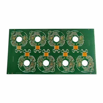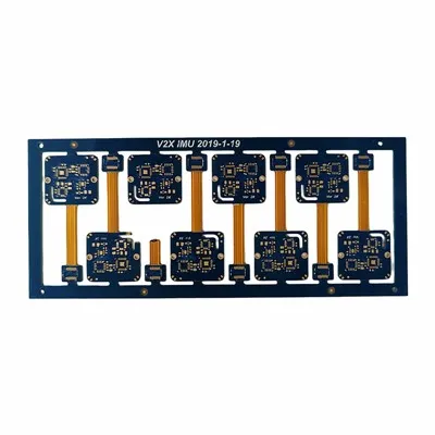
Rigid-flex boards are widely used in compact electronic products that require strong mechanical support, flexible interconnection, stable signal transmission, and reduced internal wiring. Compared with standard rigid PCB projects, the assembly process for rigid-flex boards is more complex because the product includes both rigid areas for component mounting and flexible areas for bending, folding, or module connection. Customers usually do not only ask whether components can be mounted; they want to know whether the assembled board can remain stable after soldering, handling, bending, installation, and long-term use.
Our Rigid-Flex PCB Assembly service is designed for medical devices, consumer electronics, automotive electronics, camera modules, sensors, wearable devices, industrial control systems, and other compact electronic products. We focus on assembly stability, fixture support, rigid-flex transition control, bend area protection, SMT process control, solderability, engineering review, testing, and scalable production support. The goal is to help customers reduce common risks such as board deformation, solder joint failure, connector instability, transition area cracking, poor bending performance, and inconsistent batch quality.
For many customers, the biggest pain point is that a prototype may work well in early testing, but problems appear during pilot production or mass production. Therefore, we support the full process from early DFM/DFA review to prototype builds, small-batch validation, and volume manufacturing.
Assembly Stability
Assembly stability is one of the most important concerns for rigid-flex projects. Because the board includes flexible areas, it may not stay as flat as a standard rigid board during solder paste printing, component placement, reflow soldering, inspection, or handling. If the board is not properly supported, customers may face component shift, uneven solder paste, poor connector alignment, solder bridging, weak solder joints, or assembly yield loss.
To improve assembly stability, the process must consider board structure, panelization method, carrier design, local support, component layout, and reflow conditions. For products with fine-pitch components, connectors, sensors, or BGA packages, even a small movement during SMT can affect the final result. This is why stable tooling and clear production requirements are important from the beginning.
|
Customer Pain Point |
Assembly Focus |
|
Board moves during SMT |
Use proper carrier or fixture support |
|
Components shift after placement |
Improve panel design and placement stability |
|
Connector area is unstable |
Add local reinforcement or support |
|
Flexible area is damaged during handling |
Control handling method and packaging |
|
Prototype works but batch quality varies |
Build repeatable process documentation |
A stable assembly process helps customers reduce rework, improve functional testing success, and prepare for smoother mass production.
Fixture Support
Fixture support is often necessary for rigid-flex boards because the flexible sections may bend, move, or sag during production. A suitable fixture or carrier helps keep the board flat and stable during solder paste printing, pick-and-place, reflow soldering, and inspection. Without proper support, the flexible area may create positioning errors or mechanical stress.
Fixture design should match the board structure and component layout. For example, rigid areas with dense components need stable support during placement, while flexible areas should be protected from pulling or compression. Connector areas may also require additional support to prevent deformation during soldering or later installation.
For customers seeking Rigid-Flex Circuit Assembly, fixture support is not only a production aid; it is a key factor that affects soldering quality, dimensional control, and repeatability. Good fixture planning can help reduce defects and improve yield, especially when moving from prototype to larger production volumes.

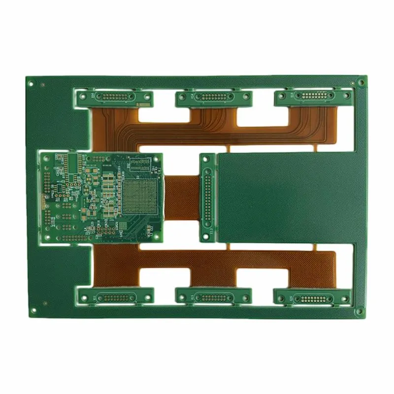
Rigid-Flex Transition Control
The rigid-flex transition area is one of the most sensitive parts of the entire board. This is the point where the rigid section and flexible section meet, and it can easily become a stress concentration area if the design or assembly process is not controlled properly. Customers often worry about cracking, delamination, copper fatigue, or open circuits near this area.
During engineering review, the transition area should be checked carefully. Components, heavy connectors, solder joints, vias, and sharp structural changes should not be placed too close to high-stress zones. The coverlay, stack-up, copper routing, and bend direction must also be considered.
Proper transition control helps reduce hidden reliability risks. Some failures may not appear during visual inspection but may occur after installation, vibration, bending, or long-term operation. For applications such as medical devices, automotive electronics, and wearable products, transition reliability is especially important.
Bend Area Protection
Bend area protection is another major concern for customers. The flexible area may need to bend during installation or remain folded inside the product. If the bend area is not designed or handled correctly, the board may suffer from copper cracking, coverlay damage, delamination, or intermittent electrical failure.
In most cases, components, solder joints, connectors, and vias should be kept away from active bending areas. The bend radius should match the material, copper thickness, layer structure, and final application. Static bending and dynamic bending also require different design considerations. Static bending usually happens during installation and then remains fixed, while dynamic bending involves repeated movement during product use.
During assembly planning, bend areas should be protected from unnecessary force, fixture pressure, and handling damage. Proper packaging is also important to prevent accidental folding or stress during transportation.

SMT Process Control
SMT process control directly affects soldering quality and final product reliability. Rigid-flex boards may include fine-pitch ICs, connectors, sensors, LEDs, BGA packages, or small passive components. Each component type may require different attention during solder paste printing, placement, and reflow.
Important process factors include stencil design, solder paste volume, placement accuracy, reflow profile, board support, and surface finish condition. If solder paste is uneven or the board shifts during placement, defects such as insufficient solder, bridging, tombstoning, or component offset may occur.
For BGA or hidden solder joints, X-ray inspection may be required depending on the project. For connector-heavy products, mechanical alignment and solder joint strength should be checked carefully. Strong SMT process control helps customers reduce assembly defects and improve first-pass yield.

Solderability
Solderability is a key concern because poor soldering may cause weak joints, intermittent failure, connector problems, or product instability. Surface finish, pad design, component type, storage condition, solder paste, and reflow profile can all affect soldering results.
Common surface finishes include ENIG, OSP, immersion silver, and lead-free HASL, depending on the product requirements. ENIG is often selected for fine-pitch components and higher-reliability applications because it provides a flat surface. OSP may be suitable for cost-sensitive projects with controlled storage and assembly conditions.
Good solderability is not only about making the board look acceptable after reflow. It also affects long-term reliability, especially when the product will experience bending, vibration, temperature changes, or repeated use.
DFM/DFA Review
DFM and DFA review are essential before production. Many problems begin at the design stage, especially in projects that combine rigid areas, flexible sections, connectors, and compact layouts. A design may be electrically correct but still difficult to assemble reliably.
Our review can focus on component placement, bend area clearance, rigid-flex transition risk, connector support, pad design, panelization, fixture requirement, surface finish suitability, test point access, and final installation direction. This helps customers find possible issues before production begins.
A reliable Rigidflex PCB Assembly project should consider manufacturability, assembly method, mechanical stress, testing plan, and future production consistency at the same time. Early engineering review helps reduce redesign, shorten development time, and improve production success.
Quality Testing
Quality testing should cover both electrical performance and assembly reliability. Customers want to know whether the finished product can pass inspection, work properly, and remain stable after installation. For rigid-flex boards, testing should also consider bend area protection and transition area reliability.
|
Quality Control Item |
Purpose |
|
Incoming PCB inspection |
Check board quality before assembly |
|
Component verification |
Reduce wrong-part and mismatch risks |
|
AOI inspection |
Detect component shift and solder defects |
|
X-ray inspection if required |
Check BGA and hidden solder joints |
|
Electrical testing |
Reduce open and short circuit risks |
|
Functional testing if required |
Verify final product performance |
|
Connector inspection |
Check contact and soldering reliability |
|
Final visual inspection |
Confirm appearance and handling quality |
A complete quality testing plan helps reduce customer-side failures, improve assembly confidence, and support stable repeat orders.
Prototype to Mass Production
Many customers start with prototype assembly to verify mechanical fit, electrical function, bend behavior, and component layout. After the prototype is approved, the project may move to small-batch testing, pilot production, and mass production. Each stage has different priorities.
During the prototype stage, fast feedback and risk identification are important. During pilot production, process repeatability and yield become more important. During mass production, customers care about stable quality, delivery reliability, cost control, and batch consistency.
We support customers through each stage by keeping engineering records, assembly requirements, fixture methods, inspection standards, and material information clear. This helps reduce the risk of a successful sample becoming unstable in volume production.
Cost and Yield Optimization
Cost and yield are closely connected. Choosing the lowest-cost assembly method may increase rework, reduce reliability, or create hidden failures. On the other hand, over-designing the process may increase cost unnecessarily. The best solution should balance reliability, assembly efficiency, and production cost.
Cost and yield can be optimized through better panelization, suitable fixture support, improved component layout, proper surface finish selection, clear testing requirements, and early engineering review. For example, keeping components away from bend areas can reduce failure risk. Adding support only where needed can improve stability without unnecessary material cost. Using the right inspection method can reduce shipment risk and avoid expensive rework later.
The goal is to reduce total project cost, not only unit price. Higher yield, fewer defects, and smoother production can save customers more time and money in the long term.
FAQ
Q1: Why is assembling rigid-flex boards more difficult than standard rigid PCB assembly?
Because rigid-flex boards include both rigid and flexible areas, they require careful fixture support, bend area protection, transition area review, and SMT process control. Without proper planning, the board may deform, components may shift, or the flexible section may be damaged.
Q2: Do rigid-flex boards need special fixtures during SMT?
In many cases, yes. Fixtures or carriers help keep the board flat and stable during solder paste printing, component placement, reflow soldering, and inspection. This improves placement accuracy and soldering quality.
Q3: Can components be placed in the bend area?
It is generally not recommended to place components, solder joints, vias, or connectors in active bending areas. Keeping these features away from bend zones helps reduce stress and improves long-term reliability.
Q4: What are the common quality risks?
Common risks include component shift, poor solder joints, connector misalignment, transition area stress, flex area damage, open circuits, short circuits, and inconsistent batch quality.
Q5: What files are needed for a quotation?
Customers usually need to provide Gerber files, BOM, pick-and-place file, assembly drawing, quantity, testing requirements, surface finish, component notes, and final application details.
Q6: Can prototypes move into mass production later?
Yes. Prototype builds can be followed by pilot production and mass production. Keeping process records, fixture methods, inspection standards, and engineering requirements consistent helps improve repeatability.
Q7: How can assembly yield be improved?
Yield can be improved through early DFM/DFA review, proper fixture support, optimized panelization, suitable surface finish, controlled SMT process, adequate testing, and careful handling of bend and transition areas.
Hot Tags: rigid flex PCB assembly, China rigid flex PCB assembly manufacturers, suppliers, factory