Solar inverters convert DC power generated by solar panels into usable AC power. During this process, power devices such as MOSFETs, IGBTs, rectifier diodes, transformers, control ICs, and high-current connectors may generate significant heat. In many inverter designs, the internal space is compact, and the system may operate in outdoor cabinets, rooftops, industrial installations, or high-temperature environments. This makes thermal management one of the most important concerns during PCB design and material selection.
Our Solar Power Inverter PCB manufacturing service is focused on solving practical customer problems, including excessive temperature rise, limited current-carrying capacity, dielectric breakdown risk, poor solderability, board warpage, unstable batch quality, and difficulty in matching PCB specifications with real inverter working conditions. Instead of offering only standard board options, we support customized material selection and engineering review based on voltage, current, power density, installation method, and assembly process.
For solar inverter customers, the key question is not simply whether the board can be produced. The real concern is whether the board can remain stable after long-term operation, thermal cycling, high current load, and repeated production batches. That is why we focus on thermal conductivity, dielectric reliability, copper thickness control, surface finish quality, dimensional accuracy, and strict final inspection.
Heat Dissipation for High-Power Inverter Systems
Heat dissipation is one of the biggest pain points in solar inverter PCB design. Inverters usually operate for long hours, and many applications require stable performance under high ambient temperature. If heat is concentrated around power components, the system may experience reduced efficiency, solder joint fatigue, component degradation, or shutdown caused by thermal protection.
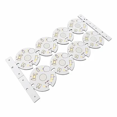
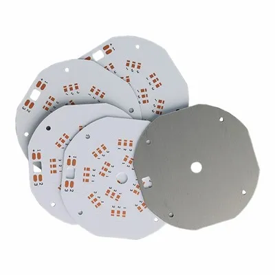
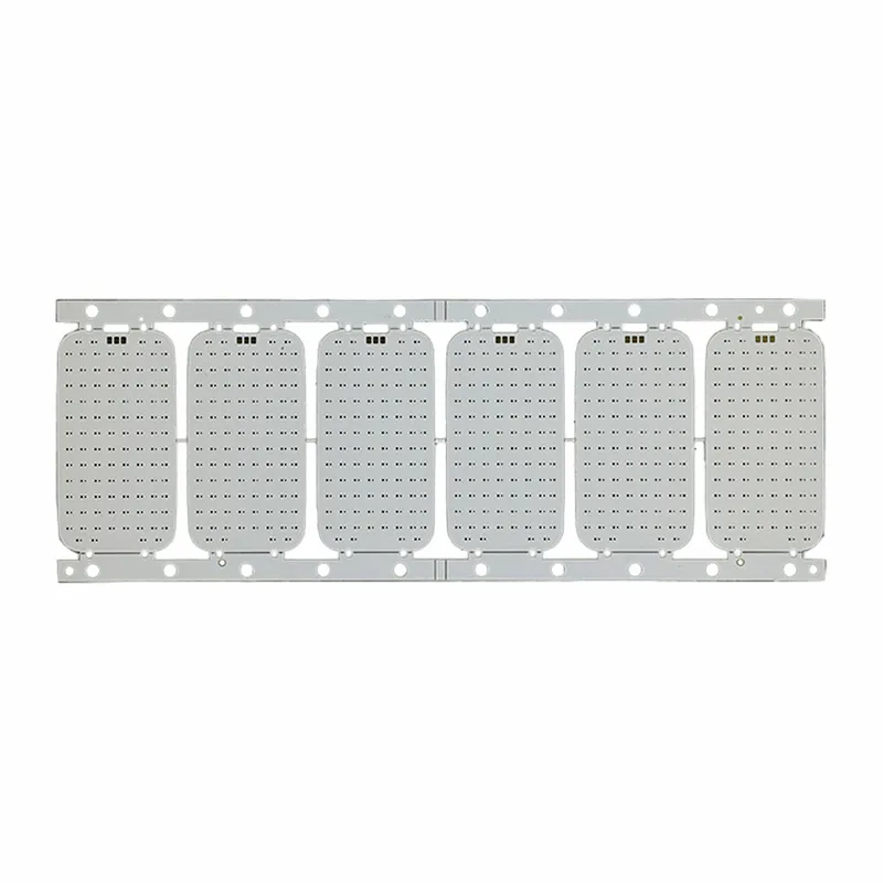
An aluminum PCB provides a more efficient thermal path. Heat generated by components moves from the copper circuit layer through the dielectric layer to the aluminum base, where it can be spread and transferred to the housing, heat sink, or other cooling structure. This helps reduce local hot spots and supports stable inverter performance.
Customers often ask whether the PCB can support their actual current, voltage, and thermal load. The answer depends on several factors, including copper thickness, trace width, dielectric thermal conductivity, dielectric thickness, aluminum base thickness, component layout, and the final mechanical installation. For this reason, we recommend reviewing the complete application environment instead of selecting a board only by one parameter.

Voltage Resistance and Insulation Safety
Because aluminum is conductive, insulation safety is critical. The dielectric layer must isolate the copper circuit from the aluminum base while still allowing heat to transfer efficiently. If the insulation layer is not suitable, the board may face leakage current, dielectric breakdown, short circuit, or long-term safety risks.
This is especially important for inverter systems because they may involve high voltage input, high current output, and continuous switching operation. Customers need to consider dielectric strength, insulation resistance, creepage distance, clearance, working voltage, and safety margin during the PCB design stage.
A reliable High Power Aluminum PCB for Inverter should not focus only on thermal conductivity. In some cases, choosing a very high thermal conductivity material without checking dielectric strength may create hidden safety risks. The correct solution should balance heat dissipation, electrical insulation, mechanical strength, and cost.
Current Stability and Copper Thickness
Current stability directly affects heat generation, voltage drop, and long-term inverter reliability. If copper thickness is insufficient or trace width is not properly designed, the circuit may generate additional heat during operation. This can reduce conversion efficiency and increase the risk of local overheating.
For power electronics applications, copper thickness selection should match the actual current load and circuit layout. Common copper options include 1oz, 2oz, 3oz, or customized copper thickness. Higher copper thickness can improve current-carrying capacity, but it may also affect production cost, etching precision, and design rules. Therefore, copper thickness should be selected based on electrical performance and manufacturability.
We can review Gerber files, power paths, component placement, and customer specifications to help confirm whether the design is suitable for production. This helps customers avoid problems such as voltage drop, excessive temperature rise, unstable power output, or unnecessary material cost.
Thermal Stability and Long-Term Reliability

Solar energy systems are expected to work for many years. A PCB used in inverter equipment must remain stable under repeated heating and cooling, long operating hours, and possible outdoor temperature changes. Customers often worry about delamination, dielectric aging, solder mask discoloration, copper separation, warpage, solder joint fatigue, and inconsistent performance after long-term use.
Thermal stability depends on the entire PCB structure, not only the aluminum base. The dielectric layer, copper bonding strength, solder mask performance, surface finish, and lamination quality all affect reliability. For inverter products, the board may pass a short functional test but fail later if the material structure is not suitable for real working conditions.
Our aluminum PCB manufacturing process pays attention to material matching, bonding stability, copper thickness control, surface finish quality, and final inspection. This helps reduce long-term failure risks and supports more stable performance in renewable energy equipment.
Technical Parameters
|
Item |
Available Options / Manufacturing Capability |
|
Product Type |
Aluminum PCB / Metal Core PCB |
|
Application |
Solar inverter, PV inverter, energy storage inverter, power control board |
|
Layer Count |
1 layer, 2 layers, customized structure |
|
Base Material |
Aluminum substrate / metal core material |
|
Thermal Conductivity |
1.0W/mK, 1.5W/mK, 2.0W/mK, 3.0W/mK or customized |
|
Copper Thickness |
1oz, 2oz, 3oz or customized |
|
Board Thickness |
0.8mm–3.2mm or customized |
|
Surface Finish |
HASL, lead-free HASL, ENIG, OSP |
|
Solder Mask |
White, black, green, blue, customized |
|
Testing |
AOI, electrical test, dimensional inspection, visual inspection |
|
Production Type |
Prototype, small batch, and mass production |
Application Areas
Aluminum PCBs are widely used in inverter and power conversion products where heat dissipation, insulation, and current stability are essential. Our Power Electronics Aluminum PCB for Solar solutions are suitable for customers developing renewable energy products that require reliable thermal management and stable electrical performance.
|
Application |
Main Customer Concern |
PCB Manufacturing Focus |
|
Solar inverter module |
High heat and continuous operation |
Thermal conductivity, copper thickness, dielectric reliability |
|
PV power conversion board |
Current load and voltage stability |
Trace design, copper control, insulation safety |
|
Energy storage inverter |
Safety and long-term reliability |
Dielectric strength, material stability, final testing |
|
Inverter control board |
Compact layout and stable signal control |
Dimensional accuracy, solderability, process consistency |
|
DC-AC power module |
Heat concentration and component aging |
Aluminum base, thermal dielectric layer, surface finish |
|
Renewable energy equipment |
Batch quality and service life |
Quality control, material consistency, production records |
Custom Manufacturing Capability
Different inverter projects require different PCB structures. A low-power control board may not need the same copper thickness or thermal conductivity as a high-power conversion module. A cost-sensitive project may require a balanced material option, while a premium inverter product may require better insulation, higher thermal conductivity, or ENIG surface finish.
We provide customized manufacturing based on customer Gerber files, drawings, samples, and technical requirements. Our engineering support can include material recommendation, copper thickness review, routing manufacturability check, surface finish selection, and production process evaluation.

For Aluminum PCB for Inverter Control Boards, we can support customized board thickness, copper thickness, thermal conductivity, dielectric layer, solder mask color, surface finish, hole size, outline shape, and production quantity. We also support prototype testing, pilot production, and stable repeat orders for mass production.
The goal of customization is to help customers find the right balance between performance, safety, manufacturability, and cost. Over-specification may increase cost unnecessarily, while under-specification may create reliability risks. We help customers choose practical specifications based on real application conditions.

Quality Control Process
Our quality control process can include incoming material inspection, copper thickness verification, drilling inspection, solder mask inspection, surface finish inspection, AOI inspection, electrical testing, dimensional measurement, visual inspection, and final packaging protection. For projects with special requirements, insulation testing or additional reliability-related checks can be discussed.
For repeat orders, process stability is especially important. Customers need every batch to match the approved sample as closely as possible. We focus on controlled production parameters, stable material sourcing, clear inspection standards, and final shipment review to support consistent quality from prototype to mass production.
FAQ
Q1: Why is aluminum PCB recommended for solar inverter applications?
Aluminum PCB is recommended because solar inverters generate heat during power conversion, especially around MOSFETs, IGBTs, diodes, and other power components. If this heat remains concentrated on the board, it can reduce efficiency, shorten component life, and increase failure risk. Aluminum PCB helps transfer heat away from the circuit layer more effectively than many standard PCB materials, making it suitable for inverter products that require long-term stable operation.
Q2: What thermal conductivity should I choose for an inverter aluminum PCB?
The right thermal conductivity depends on power level, component layout, heat source concentration, installation structure, and operating environment. A standard inverter control board may use a balanced material, while a high-power module may require higher thermal conductivity. Customers should not select the highest value blindly, because dielectric strength, thickness, cost, and manufacturability also matter. We can review your Gerber file and application conditions to recommend a practical option.
Q3: How do I know if the PCB can handle my working current?
Current capacity depends on copper thickness, trace width, copper area, temperature rise requirements, and circuit design. If the copper is too thin or the trace is too narrow, the board may generate extra heat and cause voltage drop. For inverter applications, we suggest checking the main power paths carefully before production. We can support copper thickness and manufacturability review based on your design files.
Q4: Why is dielectric strength important in aluminum PCB?
The aluminum base is conductive, so the dielectric layer must safely separate the copper circuit from the metal substrate. If dielectric strength is insufficient, the board may face leakage current, breakdown, or short circuit risk. This is especially important for inverter and power electronics products because they may work under higher voltage and continuous electrical stress. A good design should balance thermal conductivity and insulation safety.
Q5: Which surface finish is better for solar inverter aluminum PCB?
The best surface finish depends on assembly requirements and product positioning. Lead-free HASL is commonly used for practical and cost-effective production. ENIG provides a flatter surface and is suitable for fine-pitch components or higher-reliability applications. OSP may be used for cost-sensitive projects, but storage and assembly conditions should be controlled. We can recommend a surface finish based on your component type and soldering process.
Q6: Can you support prototype and mass production?
Yes. We support prototype samples, small batch production, and mass production. Prototype production helps customers verify design, material selection, assembly performance, and thermal behavior before committing to larger orders. Once the sample is approved, we can maintain production consistency through material control, process inspection, and final quality checks.
Hot Tags: solar inverter aluminum PCB, China solar inverter aluminum PCB manufacturers, suppliers, factory