
Product Details
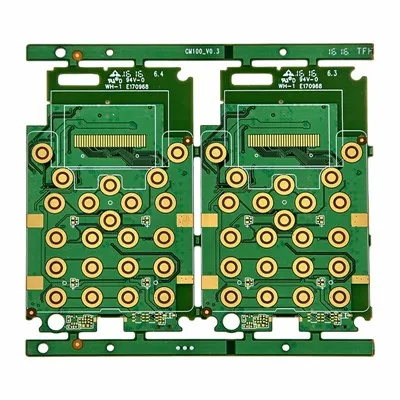
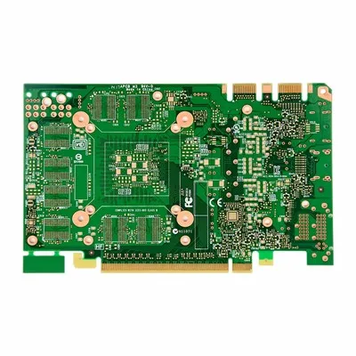
High-Frequency PCBs are specialized circuit boards designed for RF, microwave and high-speed signal applications. They adopt low-loss dielectric materials with stable dielectric constant (Dk) and low dissipation factor (Df), minimizing signal attenuation, phase shift and impedance variation at high operating frequencies. Unlike conventional FR-4 PCBs, high-frequency PCBs place strict requirements on material consistency, copper surface roughness, stack-up precision and impedance control. Typical applications include antenna modules, radar systems, communication base-station units and high-speed wireless hardware. High-frequency materials carry higher costs and limited supplier processing capacity. Engineers and buyers must evaluate frequency range, impedance tolerance, material grade and cost budget to avoid over-specification while meeting RF performance goals.

Limitations of Standard FR4 for RF Designs
FR4 remains the most common PCB substrate in the electronics industry, but it was not originally designed for microwave and RF applications.
As operating frequency increases, several limitations begin to appear:
- Higher dielectric loss
- Increased signal attenuation
- Impedance instability
- Greater insertion loss
- Reduced transmission efficiency
- More difficult signal control
In low-frequency industrial products, these issues may be insignificant. In communication equipment operating at several gigahertz, however, they can directly affect product performance.
This is why many RF designs transition from standard FR4 to specialized high-frequency materials.

Understanding Dielectric Constant and Loss Tangent
When evaluating High Frequency PCB materials, two parameters receive significant attention.
♦ Dielectric Constant (Dk)
The dielectric constant affects signal propagation speed and impedance calculations.
Materials with stable Dk values help engineers achieve more predictable electrical performance.
♦ Loss Tangent (Df)
Loss tangent measures how much signal energy is lost as heat during transmission.
Lower Df values generally result in:
Reduced signal loss
Better transmission efficiency
Improved long-distance signal performance
Enhanced RF system stability
For high-frequency applications, Df is often more important than many buyers initially realize.
A material with excellent thermal performance but poor loss characteristics may still fail to meet RF requirements.
Criteria for High‑Frequency PCB Material Adoption
Not every communication product requires specialized laminates.
The following applications commonly benefit from High Frequency PCB technology:
5G Communication Equipment
Base stations, antennas and communication modules often operate at frequencies where signal loss becomes a critical design factor.
01
Radar Systems
Automotive radar and industrial sensing equipment require accurate signal transmission and reflection analysis.
02
Satellite Communication Devices
Long-distance communication systems depend on low-loss signal paths.
03
RF Power Amplifiers
High-frequency amplification circuits benefit from stable dielectric performance.
04
Aerospace and Defense Electronics
Mission-critical communication equipment often demands predictable RF performance under challenging conditions.
For many industrial products operating below these requirements, standard FR4 may still provide an acceptable and more economical solution.
05
Material Comparison: FR4 vs High Frequency PCB
One of the most common sourcing questions concerns whether specialized materials justify their higher cost.
The answer depends on performance requirements.
|
Item |
Standard FR4 |
High Frequency PCB |
|
Material Cost |
Low |
Higher |
|
Dielectric Stability |
Moderate |
Excellent |
|
Signal Loss |
Higher |
Lower |
|
RF Performance |
Limited |
Excellent |
|
Impedance Consistency |
Moderate |
High |
|
Microwave Applications |
Limited |
Suitable |
Although high-frequency materials increase PCB cost, they often prevent expensive redesigns and performance failures later in development.
Common Material Options
Several laminate systems are widely used for high-frequency applications.
Typical material categories include:
- PTFE-based materials
- Hydrocarbon ceramic materials
- Modified epoxy laminates
- Low-loss composite materials
- Hybrid multilayer structures
Each material offers a different balance of cost, manufacturability and electrical performance.
Rather than selecting the highest-performing material available, successful projects typically choose the material that best matches actual frequency requirements.
Design Risks That Buyers Should Understand
Many RF projects experience delays not because of manufacturing defects but because material selection occurs too late in the design process.
Several common mistakes include:
√ Selecting Materials Based Solely on Price
A lower-cost material may increase signal loss and require expensive redesigns.
√ Over-Specifying Material Performance
Choosing premium RF materials for moderate-frequency applications may increase costs without improving product functionality.
√ Ignoring Stack-Up Design
Material selection and stack-up design must work together to achieve impedance targets.
√ Inadequate Signal Simulation
Simulation helps identify potential performance issues before fabrication begins.
Addressing these factors early often reduces development costs and accelerates product qualification.
Verification and Testing Methods
Unlike many conventional PCB projects, high-frequency designs often require electrical validation beyond standard continuity testing.
Common verification methods include:
√ Impedance Testing
Confirms that transmission lines meet specified impedance requirements.
√ Network Analyzer Measurements
Used to evaluate insertion loss and return loss characteristics.
√ Signal Integrity Analysis
Helps verify transmission performance under actual operating conditions.
√ Environmental Reliability Testing
Ensures performance remains stable under temperature and humidity variations.
For RF products, successful validation is often just as important as successful manufacturing.
Future Trends in High Frequency PCB Technology
Several industries continue driving demand for advanced RF materials:
- 5G and future communication networks
- Autonomous vehicle radar systems
- Satellite internet infrastructure
- Industrial wireless automation
- Aerospace communication platforms
As operating frequencies continue to increase, PCB materials must deliver lower loss, improved stability and more predictable electrical performance.
Manufacturers capable of supporting advanced RF materials and controlled impedance production will be better positioned to meet future market requirements.
FAQ
What is a High Frequency PCB?
A High Frequency PCB is a printed circuit board manufactured using low-loss materials designed to support RF, microwave and high-speed signal applications.
Is FR4 suitable for high-frequency circuits?
FR4 can support some communication products, but specialized high-frequency materials generally provide better signal integrity and lower transmission loss at higher frequencies.
Which industries commonly use High Frequency PCBs?
Telecommunications, radar systems, aerospace, satellite communications, automotive radar and industrial wireless systems frequently use high-frequency PCB technology.
Are High Frequency PCBs more expensive?
Yes. Specialized materials generally cost more than standard FR4 laminates, but they can significantly improve RF performance.
Hot Tags: high frequency pcb, China high frequency pcb manufacturers, suppliers, factory, rigid printed circuit board, rigid rigid and flexible pcb