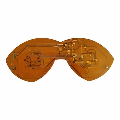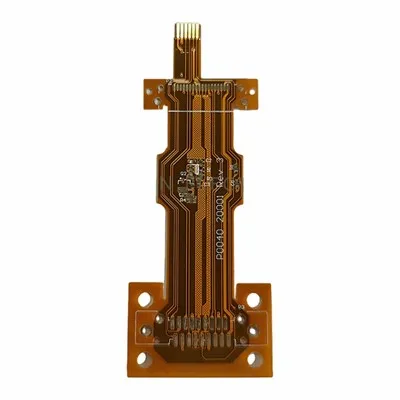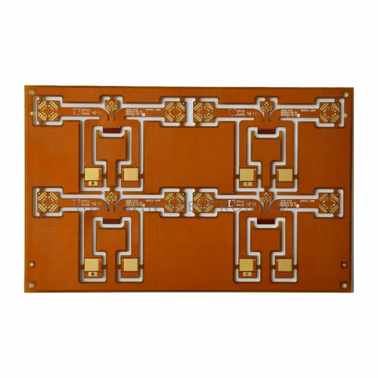
Flexible printed circuit boards are designed for electronic products that require compact structure, lightweight design, flexible installation, and reliable electrical connection between different modules. Compared with traditional rigid PCBs, flexible circuits can bend, fold, and fit into limited spaces, making them ideal for modern electronic devices such as wearable products, medical devices, automotive electronics, camera modules, sensors, battery packs, display modules, and compact consumer electronics.
For many customers, the biggest concern is not only whether the board can be manufactured, but whether it can remain reliable after bending, assembly, and long-term use. Common pain points include broken traces in the bending area, unstable soldering, incorrect material selection, poor dimensional accuracy, connector area deformation, and high production cost. Our flexible PCB solutions focus on these practical concerns, helping customers balance flexibility, reliability, manufacturability, and cost from prototype to mass production.
Whether the project requires a simple single-sided FPC Board, a double-sided flexible circuit, or a more complex multilayer flexible design, we can provide material recommendations, engineering review, stiffener support, quality inspection, and production support according to the final application.
Flexibility
Flexibility is the core advantage of flexible printed circuit boards. It allows electronic products to reduce internal wiring, save space, simplify assembly, and improve structural freedom. For products with limited internal space, such as wearable devices, smartphones, camera modules, and medical sensors, flexible circuits can connect different functional modules without using bulky wires or connectors.

However, flexibility must be designed correctly. Customers often ask how much the board can bend, whether it can be folded during installation, and whether it can support repeated movement. The answer depends on material type, copper thickness, circuit layout, bending radius, stack-up thickness, and whether the application is static or dynamic. A flexible circuit used only during installation has different requirements from one used in repeated bending or movement.
Our engineering review helps customers evaluate bending areas before production. By checking trace direction, copper thickness, coverlay design, and bend radius, we help reduce the risk of copper cracking, open circuits, and mechanical stress failure.

Bend Reliability
Bend reliability is one of the most important concerns for flexible PCB customers. A board may look good after production, but if the bending area is not designed properly, it may fail during assembly or after long-term use. Typical problems include broken copper traces, coverlay cracking, delamination, pad lifting, and unstable electrical connection.
For better bend reliability, the flexible area should avoid unnecessary vias, sharp trace corners, and sudden thickness changes. Traces in the bending area should be routed smoothly, and the bending radius should match the material structure and copper type. For dynamic bending applications, material selection becomes even more important because repeated movement places continuous stress on the copper layer.
A reliable Flex Board PCB should be designed with both electrical performance and mechanical movement in mind. We help customers review bending zones and recommend suitable structures based on whether the product requires one-time bending, fixed installation, or repeated flexing during use.

Material Selection
Material selection directly affects flexibility, heat resistance, thickness, signal performance, solderability, and cost. Many customers are unsure whether to choose PI, PET, LCP, RA copper, ED copper, or special coverlay structures. The best option depends on the product application, working environment, bending requirement, and budget.
|
Material / Structure |
Main Feature |
Suitable Application |
|
Polyimide PI |
Good heat resistance and flexibility |
Wearable devices, medical electronics, automotive electronics, sensors |
|
PET |
Cost-effective for simple flexible circuits |
Low-cost electronic products and simple connection designs |
|
LCP |
Good high-frequency performance and low moisture absorption |
Antennas, communication modules, high-frequency applications |
|
RA Copper |
Better bending performance |
Dynamic bending, folding structures, wearable products |
|
ED Copper |
Cost-effective and suitable for static bending |
Fixed installation and low-movement applications |
|
PI Coverlay |
Protects circuits and improves flexibility |
Most flexible PCB designs |
|
Stiffener Material |
Adds support to selected areas |
Connector areas, soldering areas, component mounting zones |
The most suitable material is not always the highest-cost material. For example, a static installation product may not require RA copper, while a wearable device with repeated bending may need a more flexible copper structure. We help customers choose a practical material solution based on reliability requirements and cost targets.
Thin & Lightweight Design
Thin and lightweight design is another major reason customers choose flexible printed circuit boards. In modern electronics, product size and weight are critical. Flexible circuits can replace traditional wire harnesses and reduce unnecessary connectors, helping product designers create thinner and more compact structures.
For portable devices, wearable electronics, and medical sensors, thinner circuits can improve comfort, reduce internal space pressure, and support more creative product designs. However, making a board thinner also requires careful control. If the structure is too thin for the application, it may affect handling, assembly, or long-term durability. If it is too thick, flexibility may decrease and bending stress may increase.
We help customers balance thickness, flexibility, mechanical strength, and manufacturability. By reviewing the stack-up, coverlay, copper thickness, and stiffener requirements, we can recommend a structure that supports both product design and production stability.

Stiffener Support
Although flexible circuits are designed to bend, some areas need extra support. Connector areas, soldering pads, gold finger areas, and component mounting zones often require stiffeners to improve mechanical strength and assembly stability. Without proper stiffener design, the board may deform during assembly, causing poor soldering, weak connector contact, or handling damage.
Common stiffener options include PI, FR4, stainless steel, and aluminum. PI stiffeners are thin and flexible, FR4 stiffeners are widely used for connector and soldering areas, stainless steel provides strong mechanical support, and aluminum can be considered for special structural or thermal needs.
Proper stiffener design can improve product reliability without sacrificing the flexibility of the entire board. We can help customers choose stiffener material, thickness, location, and bonding method according to the assembly process and final product structure.
Assembly Stability
Assembly stability is a key pain point because flexible circuits are thin and soft. During SMT assembly or manual installation, the board may shift, deform, or become difficult to position. Customers often worry about soldering defects, connector misalignment, pad damage, or low production yield.
The Flexible PCB Assembly Process requires good control of panel design, tooling, stiffener placement, surface finish, solder mask or coverlay openings, and packaging protection. If these details are not handled properly, even a well-designed circuit may create problems during assembly.
We support assembly-friendly flexible PCB design by reviewing pad layout, stiffener areas, panelization, surface finish, and dimensional tolerance. This helps customers reduce assembly risks and improve production efficiency.
Quality Control
Quality control for flexible circuits must cover both electrical and mechanical performance. In addition to open and short circuit testing, flexible PCBs require attention to coverlay alignment, adhesive condition, bending area quality, surface finish, dimensional accuracy, and appearance.
Our quality control process includes material inspection, circuit pattern inspection, coverlay inspection, copper thickness checking, surface finish inspection, electrical testing, final visual inspection, and packaging protection. For projects with special requirements, additional testing such as impedance testing or bending-related inspection can be arranged according to customer specifications.
Good quality control helps reduce hidden risks such as copper cracks, poor adhesion, short circuits, open circuits, contamination, oxidation, and deformation. For customers, this means better assembly yield, fewer product failures, and more stable long-term performance.
Prototype to Mass Production
Flexible PCB projects usually start with prototype testing because customers need to verify product structure, bending performance, assembly method, and electrical function. After the prototype is approved, the project may move to small-batch testing, pilot production, and finally mass production.
We support customers through each stage. During the prototype stage, we help check manufacturability and identify potential design risks. During small-batch production, we help confirm process stability and assembly suitability. During mass production, we focus on batch consistency, quality control, delivery stability, and cost efficiency.
Cost Optimization
Cost optimization is important because flexible PCBs can be more expensive than standard rigid PCBs. However, reducing cost should not mean sacrificing reliability. A poor material choice, unsuitable copper type, or weak stiffener design may reduce the initial price but increase failure risk, rework cost, and product return rate later.
We help customers optimize cost through practical engineering suggestions, such as choosing the right material for the actual bending requirement, avoiding unnecessary multilayer structures, optimizing panelization, selecting suitable copper thickness, and using stiffeners only where needed.
|
Cost Factor |
Optimization Direction |
|
Material Selection |
Match PI, PET, LCP, RA copper, or ED copper with real application needs |
|
Layer Structure |
Avoid unnecessary complexity when single-sided or double-sided design is enough |
|
Stiffener Design |
Use proper stiffener only in required areas |
|
Panelization |
Improve material utilization and production efficiency |
|
Surface Finish |
Choose a finish that balances solderability, shelf life, and budget |
|
Tolerance Requirements |
Avoid over-tight tolerances unless the application requires them |
FAQ
Q1: What is a flexible printed circuit board used for?
A flexible printed circuit board is used in electronic products that require lightweight structure, compact space, and flexible connection between different modules. It is commonly used in wearable devices, medical electronics, automotive electronics, camera modules, sensors, battery packs, display modules, and consumer electronics.
Q2: How do I choose the right material for a flexible PCB?
The right material depends on the application, bending requirement, working temperature, signal performance, and budget. PI is commonly used for reliable flexible circuits, PET is suitable for cost-sensitive simple designs, LCP is suitable for high-frequency applications, RA copper is better for dynamic bending, and ED copper is suitable for static bending applications.
Q3: What is the difference between static bending and dynamic bending?
Static bending means the flexible PCB is bent during installation and then remains mostly fixed. Dynamic bending means the board will bend repeatedly during product use. Dynamic bending applications usually require more careful material selection, suitable bend radius, and optimized circuit layout.
Q4: Why is bend radius important for flexible PCBs?
Bend radius directly affects bending reliability. If the bending radius is too small, it may cause copper cracking, coverlay damage, delamination, or open circuits. A proper bend radius helps improve long-term reliability and reduces mechanical stress in the bending area.
Q5: Do flexible PCBs need stiffeners?
Not every flexible PCB needs stiffeners, but stiffeners are often used in connector areas, soldering areas, gold finger areas, and component mounting zones. Proper stiffener support improves assembly stability and helps prevent deformation, pad damage, or poor connector contact.
Q6: Can you support prototype and mass production?
Yes. We support flexible PCB prototype production, small-batch testing, pilot production, and mass production. Prototype production helps customers verify structure, bending performance, and electrical function before moving to volume manufacturing.
Q7: How do you ensure flexible PCB quality?
Quality control includes material inspection, circuit pattern inspection, coverlay alignment inspection, copper thickness checking, surface finish inspection, electrical testing, final visual inspection, and packaging protection. For special projects, impedance testing or bending-related inspection can also be arranged.
Hot Tags: flexible printed circuit board, China flexible printed circuit board manufacturers, suppliers, factory